
Connectivity - the basis for local and global data exchange - Part 2
Published:
In the first part of this blogpost series, fundamental and strategical questions about connectivity have been adressed. This second part delves into the operationalization of hardware components and communication protocols essential for cloud connectivity.
1 Hardware components and transmission protocols enabling connectivity
After focusing on strategic aspects of data integration in the previous blogpost, this one focuses on operationalization. This includes examining the necessary hardware components and their communication protocols.
Regarding the question of what hardware is needed to enable cloud connectivity, every integrator has its own answer. Particularly the larger players typically try to cover the entire range with their own brand devices. For Siemens, this range of proprietary devices extends from the sensor right up to the cloud with Mindsphere, Siemens’ IoT cloud. I believe that in software development open interfaces ensure that individual providers can focus on core topics, thereby mastering them and also quickly responding to changing conditions such as emerging standards. I follow this approach with hardware as well, which is why the following illustration includes devices from various manufacturers that communicate via open standards, thus enabling modern and flexible cloud connectivity with minimal vendor lock-in.
The following illustration provides an overview of the device categories and their interactions, and illustrates individual example devices of each category.
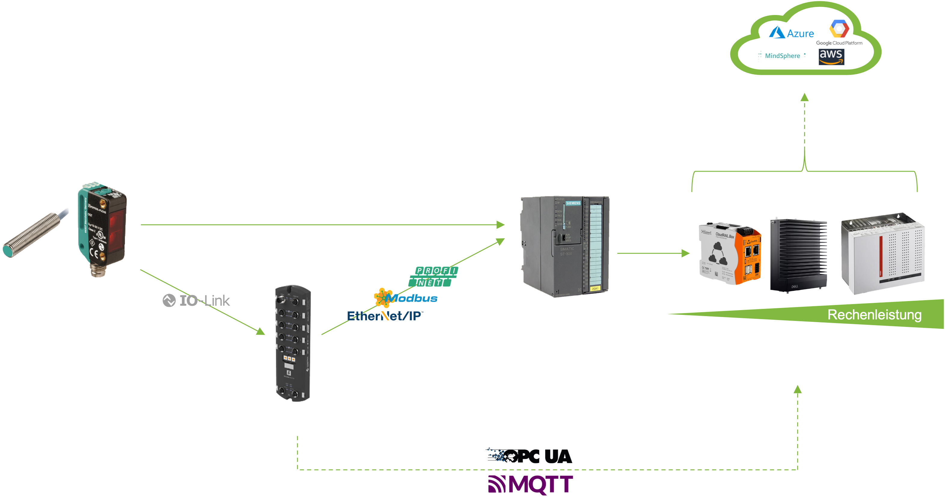
On the far left of the illustration is the sensor technology, which records the measurements directly at the machines. This illustration shows, for example, two sensors from sensor manufacturer Pepperl+Fuchs: an inductive proximity switch and a reflex light scanner — both sensors used for object detection. The range of available sensors is vast; detailed information about individual sensors can be found e.g. on Pepperl+Fuchs’ website.
The next device category in the above illustration are the network modules, which enable easy connectivity of sensors and devices to higher-level Ethernet or Industrial Ethernet networks. The illustration above features an IO-Link Master of the ICE3 generation from Pepperl+Fuchs, to which up to 8 sensors can be connected via cable. IO-Link is the dominant communication system for transmitting sensor signals, as also indicated in the above illustration. To further transmit the data to a controller, several Ethernet protocols compete, such as Profinet, Modbus TCP, EtherNet/IP, or EtherCAT. The depicted IO-Link Master of the ICE3 generation from Pepperl+Fuchs, for example, supports the protocols Profinet and Modbus TCP. However, there are also numerous network modules on the market that are specifically designed for a particular Ethernet protocol.
The next device category in the figure above is the controller. While the English term is typically PLC (Programmable Logical Controller), the term SPS (Speicherprogrammierbare Steuerung) has been established in German. The illustration features a Siemens Simatic S7 controller. Such a controller is typically located in the control cabinets of production halls.
The question then arises as to why the network module is necessary if the sensor technology can also interact directly with the controller. Although this is fundamentally possible, an analog module (terminal) is required to convert the analog sensor signal into a digital signal. If the control cabinet is not in close proximity to the sensor technology, this is impractical solely due to the cabling. Thus, a decentralized participant is required directly in the plant field. From the provider Siemens, this could be an ET 200SP or an IO-Link Master.
The latter option does not require a control cabinet, is easier to cable, enables the parameterization of sensors, and simplifies sensor exchange, which is why the future trend leans towards this option. As the network modules like the depicted IO-Link Master of the ICE3 generation are capable of storing all configurations, standalone use without an overarching SPS is also possible. Detailed application scenarios can be viewed at our sensor partner.
Next, the question arises as to how the data can additionally be transferred to the cloud alongside interaction with the controller. As the figure above shows, this is done via the device category Edge Devices. Edge Device is a collective term for local computing capacities. Sometimes, even a simple sensor is referred to as an Edge Device.
In the context of this blogpost, however, such computing units are meant, which have sufficient processor and memory capacity, etc., to operate a Linux distribution.
As the illustration shows, this can involve small computing units like the Cloudrail Box - or the popular experimental environment Raspberry Pi - or very powerful gateways or even industrial PCs.
But how do the data get to the Edge Devices? As the figure shows, there are mainly two ways:
Use of the Multilink function from the IO-Link network module Through the Multilink function of the network module, in addition to communication with a higher-level SPS e.g., via the Profinet protocol, data can simultaneously be passed to an Edge Device via OPC UA or MQTT. As the dashed arrow indicates, this transfer is wireless. Details of the OPC UA and MQTT protocols will be explained at the end of the blogpost.
Transmission of data from the controller to an Edge Device Depending on the controller, a lot of work for translations between protocols must be done at this point. This way is fundamentally possible, but if network modules are already in use (for the reasons mentioned above), the first-mentioned way might be the easier one. However, it should be mentioned here that new generations of controllers are also MQTT- or OPC UA-capable and thus this route can also make sense. In the category of Edge Devices, it is finally worth mentioning the provider CloudRail, which has established itself in recent years. The provider enables plug-and-play connection of sensors (via network modules or SPS) as SaaS (Software as a Service). A very large selection of pre-configured sensors accelerates the connection. In addition, Cloudrail also supports the way from the cloud to the Edge Device regarding Device Management.
To offer these advantages not only on Cloudrail’s own device but also to use more powerful gateways or industrial PCs, CloudRail also offers Cloudrail.OS, which operates the Cloudrail software in a container.
If a manufacturing company wants to digitalize its own production line and perform monitoring and data analysis via cloud services, the advantage of a fast cloud connection of industrial sensors often outweighs the disadvantage of dependence on another third-party provider. However, if the manufacturing company wants to digitalize its own product, the consequences of such dependence should be well examined to consciously make the decision for or against such a provider.
The last category in the illustration describes the cloud providers. All providers have in common that the data is transferred via an Edge Device. To ensure the security of the connection and prevent misuse, certificates are created in the cloud and passed on to the Edge Devices. Only if the Cloud Account and Edge Device successfully authenticate each other can data be exchanged. Data exchange between Edge Device and Cloud occurs almost exclusively via MQTT in the industrial context. The possibilities that arise from further processing of the data in the cloud will be explained in detail in some follow up blogposts about “Data Platform” and “AI Services”.
Now that the most important parts of the hardware have been explained lets have a look at the protocols that allow for the actual data exchange.
2 The most important transmission protocols in the industrial context
In the previous chapter, the protocols MQTT and OPC UA were mentioned several times, highlighting their significance in the Industrial Internet of Things (IIoT). This chapter will analyze these protocols in technical detail. They will first be contextualized within the TCP/IP model, which is a network reference model consisting of four layers: the network layer, the internet layer, the transport layer, and the application layer.
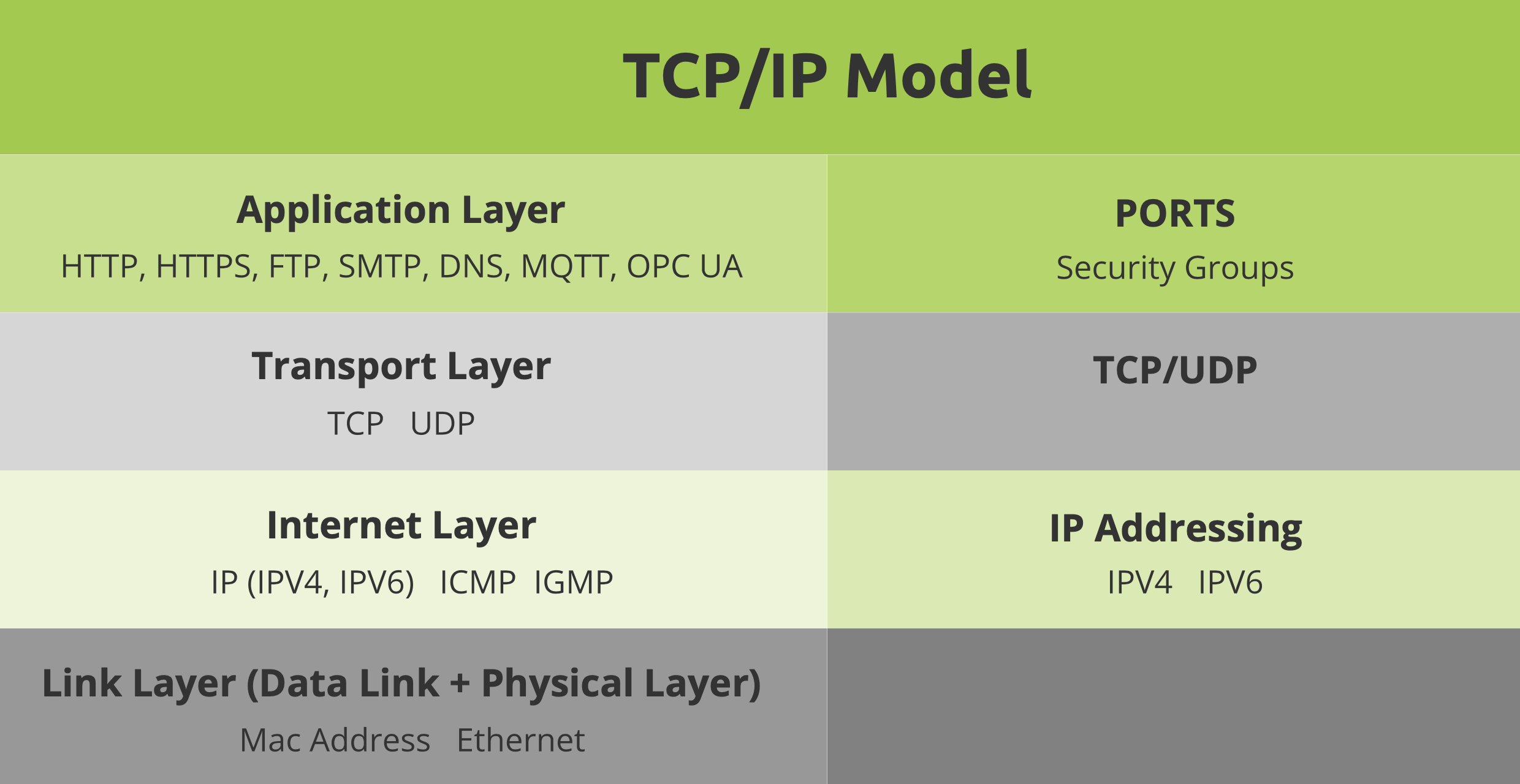
The network layer establishes the physical connection between devices and manages data exchange over this connection. The - most well-known standards of this layer are Ethernet and Wireless.
The internet layer facilitates the transmission of data packets between networks. The Internet Protocol (IP) is the most important protocol in this layer.
The transport layer is responsible for connecting endpoints and managing data flow between them, utilizing protocols like TCP and UDP.
The application layer contains protocols for data exchange between applications, such as HTTP for web browsing and SMTP for email. MQTT and OPC UA also belong to this layer.
2.1 MQTT (Message Queuing Telemetry Transport)
MQTT is a lightweight protocol, certified as an OASIS and ISO standard (ISO/IEC 20922:2016), and is commonly used in IoT applications where many devices need to communicate. It is particularly suitable in scenarios where clients require a lean code footprint and are connected to unreliable networks.
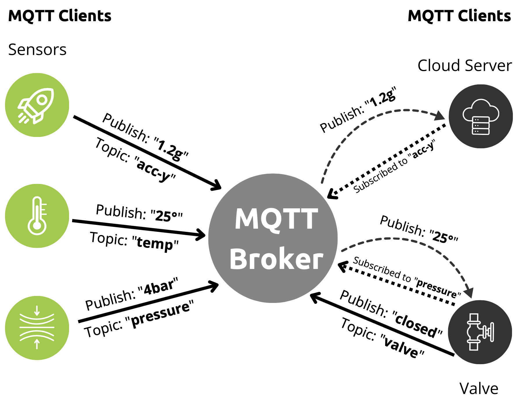
The illustration above visualizes the publish-subscriber model that underpins MQTT: A device (Client) sends messages (termed “publishes”) to a broker, which then forwards these to all devices (clients) subscribed to these messages (termed “Topics”). Each client can be a publisher, a subscriber, or both. In the illustration above, the sensors are publishers, the valve is both a publisher and a subscriber, and the cloud server is a pure subscriber. This model allows many devices to communicate simultaneously and efficiently without each device needing to communicate directly with every other device.
The main advantage lies in the decoupling of publishers and subscribers: There’s no need to establish countless individual connections; only the connection to the broker is necessary, allowing for asynchronous communication.
The key features of the MQTT specification include:
- Topic: Each message consists of a topic and a payload. The topic is the central element that allows the broker to filter messages and send them to the appropriate subscribers. Topics can include multiple levels, such as
factory1/machine4/data/pressure, with each level separated by a slash. Using placeholders, information can be aggregated; for example, subscribing tofactory1/+/data/pressuremeans subscribing to pressure values from all machines in factory 1. - Quality of Service (QoS): MQTT offers different QoS levels to adjust the quality and reliability of message transmission according to application requirements. There are three levels of QoS in MQTT:
- QoS 0: Known as “At most once.” Here, the message is sent only once without confirmation of receipt. There’s no guarantee that the message will reach the recipient or arrive in the correct order. This level has the lowest reliability but also the least network load.
- QoS 1: Known as “At least once.” In this level, the message is sent at least once, and the recipient sends an acknowledgment (ACK) back to the sender to confirm receipt. If the sender does not receive an ACK, the message is sent again. This ensures that the message arrives at least once, but it may be received multiple times.
- QoS 2: Known as “Exactly once.” This level provides the highest reliability. The message is sent exactly once, and the recipient sends a confirmation back to the sender. Additionally, a two-step handshake is used to ensure the message is received only once, even in the case of network issues or outages. QoS 2 has the highest network load due to additional overhead for confirmations and the handshake.
- Session Awareness: This refers to the MQTT broker’s ability to maintain the state of a connection between a client and the broker. It allows for reconnecting and seamless message exchange if the connection between the client and the broker is temporarily interrupted. Session Awareness is controlled by the “Clean Session” flag in the MQTT client’s connection request. There are two options:
- Clean Session = 0: This represents a persistent session. The MQTT broker stores the state of the connection, including subscriptions and message queues, if the client goes offline or the connection is interrupted. When the client reconnects, the broker resumes the previous state, and the client can continue its subscriptions and queues as if the connection had never been interrupted.
- Clean Session = 1: This represents a non-persistent session. The MQTT broker discards the state of the connection when the client goes offline or the connection is interrupted. When the client reconnects, it starts with a clean state, and the broker has no knowledge of the client’s previous subscriptions or queues.
Session Awareness is particularly useful in intermittent networks, where the connection between the client and the broker cannot be permanently maintained. By maintaining the state of the connection, clients can seamlessly exchange messages once the connection is restored without losing information.
Additional exciting specification features that were introduced with the release of MQTT 5 include Shared Subscriptions, Status Codes, security-related control packets, Topic Aliases, and message expiration dates. However, discussing these in detail would go beyond the scope of this blogpost and can be read in detail in the specification if needed.
2.2 OPC UA (Open Platform Communications Unified Architecture)
OPC UA stands for “Open Platform Communications Unified Architecture” and is an industry standard for communication and data exchange in automation technology and the Industrial Internet of Things (IIoT). It is an open, platform-independent, and vendor-neutral standard that enables interoperability between different devices, systems, and applications. OPC UA is the successor to OPC with the goal of platform independence, making it independent of Microsoft and their COM/DCOM technologies.
The significant value of OPC UA lies in its data and information models: Technical working groups define so-called Companion Specifications, aiming for cross-industry harmonization and communication among all devices. For example, numerous manufacturers of injection molding machines have defined a uniform data model for injection molding machines in a joint consortium and published the so-called Euromap77 interface, which is equivalent to a finished Companion Specification. For a machine operator, this means that an injection molding machine implementing the Euromap77 interface has a uniform data model, and data from all injection molding machines implementing this interface can be uniformly queried.
Ho does such a Data Model look like? OPC UA data modeling is based on two fundamental elements: nodes and references. Each data unit is referred to as a node, and these nodes are connected via references. There are various types of nodes and references, for example, a node could be an “Object,” “Variable,” “Method,” “ObjectType,” or “DataType.” The references also have types and are organized in hierarchical and non-hierarchical groups. The nodes and references are placed within an address space, and each node can be addressed using a unique node identifier, called “NodeId,” which serves as the address under which the corresponding data information of the node can be retrieved.
What is an Information Model? Information models provide standard node definitions to enable better harmonization among devices. There are various information models, of which the OPC Foundation has defined fundamental models such as “Data Access (DA),” “Historical Data Access (HDA),” “Alarms and Conditions,” and “Programs.” These models inform about the supported functions of an OPC UA application. The Data Access (DA) model enables standard access to process and parameter data. The Historical Data Access (HDA) model extends functionality by allowing storage of multiple measurements of the same node for statistical purposes. The Alarms and Conditions model enables the sending of events for emergency notifications, and the Programs model allows for the definition of simple state machines. The scalability of OPC UA allows for the implementation of just the DataAccess information model, which is particularly advantageous for devices with limited memory and computing power. These information models contribute to the harmonization of devices, as they implement the same information at the same access points (NodeIds), simplifying the exchange of devices, even from different vendors.
After the basics of data and information models have been explained, the question arises about the type of communication via OPC UA. It is important to distinguish between the Request/Response and the Pub/Sub patterns:
Request/Response: This pattern is a common communication pattern in client/server architectures. It is based on a simple operation: the client sends a request to the server, and the server responds with an appropriate answer. Typically, this is implemented synchronously, meaning the client waits for the server’s response before proceeding.
Pub/Sub: Since 2018, OPC UA has been expanded to include Pub/Sub communication, utilizing, among other things, MQTT for asynchronous communication, as described above in the publish-subscriber model. This is often referred to as “OPC UA over MQTT.”
The following illustration shows an OPC UA application communicating with an OPC UA client in the Request/Response model while simultaneously publishing data to an MQTT broker in the Pub/Sub system.
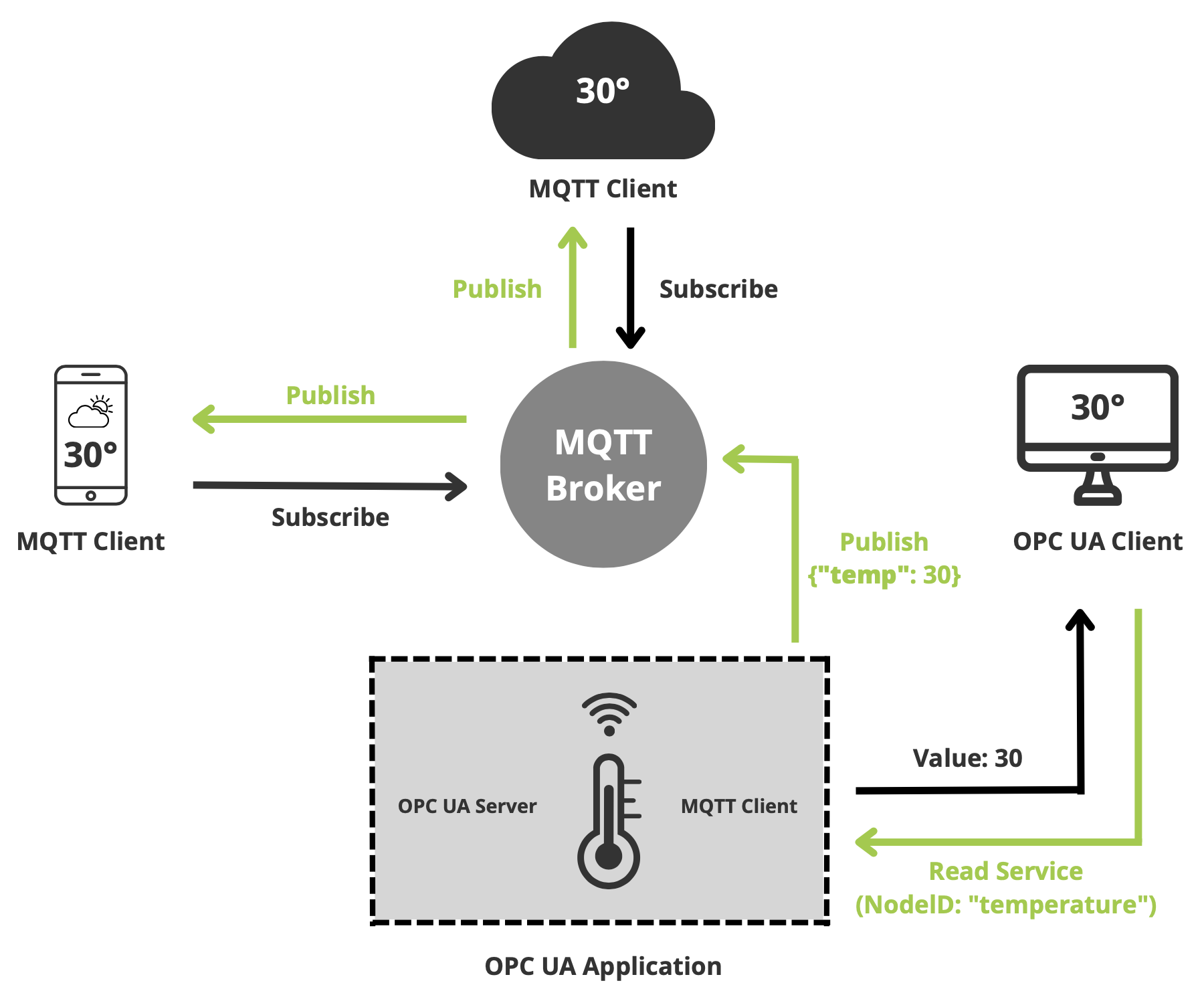
When the OPC UA client requests the value of the NodeID “temperature,” it receives a response according to the Request/Response model. Simultaneously, the temperature sensor regularly publishes its values to an MQTT broker. The two communication paths are realized using two separate TCP connections.
2.3 Protocol Comparison
After both protocols have been explained in detail, they will be compared in this subsection to develop an understanding of their optimal application areas. Interoperability encompasses both machine-machine communication and human-machine communication. The criteria examined include interoperability, real-time behavior, implementation, and use cases.
| Criteria | MQTT | OPC UA |
|---|---|---|
| Interoperability | For machine-machine communication, the protocol is insufficient as there is no semantic standardization defined. Mistyped topics or data sent in an unexpected format are not considered errors. Machine-machine communication is only possible if all topics and payloads are predefined manually. For human-machine interaction, one must first consult a manual to understand which topics are available and how their data is structured before interacting with the machine. The machine cannot decide on its own which topics can be subscribed to. | Capable of enabling machine-machine interactions, providing a variety of functions for syntactic and semantic interoperability. All devices use the same types and services for communication, utilizing information models stored in Nodeset files in a consistent format. These files contain a collection of nodes and references that define the data according to OPC UA modeling rules in a machine-readable format. Different working groups are harmonizing parameters and process data names, method availability, events, etc., to ensure that different devices have similar names and behaviors. Visualisation tools also enable human-machine interaction. |
| Real-time Behavior | MQTT is a very lean protocol and thus achieves very short transport times. If the broker is reachable (which can be ensured by redundancy) and the subscriber is connected to the publisher, the nearly real-time performance promised theoretically can be achieved. | The Pub/Sub extension allows OPC UA to compete in the real-time arena. An interesting development is OPC UA TSN (Time-Sensitive Networking), a series of sub-standards of the Ethernet standard that make data transmission over standard Ethernet capable of real-time operation. Parts of the automotive industry are already adopting this standard. |
| Implementation | Very low memory requirement. Low complexity of implementation. | Comparatively high memory requirement, which can be somewhat reduced by limiting the possible TCP connections and restricting the information models to Data Access (DA). High complexity of implementation, especially if a complete information model is to be established. |
| Use Cases | Simple, compact solutions. Low performance and memory requirement. | Standardization and harmonization of shared data. Easy interchangeability of devices through the use of identical information models. Suitable when a mix of Request/Response and Pub/Sub communication is needed. |
Leave a Comment